Pick to steam turbine generator, air compressor, oil film support of large rotating machinery, because of the installation or operation, in the process of rotor spinning, light that may occur and the wall friction and impact, referred to as "rubbing. Acoustic emission technology in fault early diagnosis happened especially with superiority. The characteristics of this system is not the traditional counts, amplitude, energy and duration of ae characteristic parameters, such as, but in the frequency of the acoustic emission signal envelope analysis for feature extraction, acoustic emission process analysis and field test show that this method is sensitive to the rubbing test, the starting stage in rubbing, spectral envelope in a dramatic increase in the periodic component and speed synchronization. According to the new design idea was developed by BUAA rubbing ae detector is introduced.
Keywords acoustic emission detection device; Fault diagnosis; Rotating mechanism; rubbing
Classification, TP 206.3
Steam turbine generator, air compressor oil film of large rotating machinery, due to various factors in the installation or operation, in the process of rotor operation, and the wall occurred slight friction and impact, called rubbing. This kind of failure, with the vibration of the conventional detection method the effect is not ideal, especially early failure is hard to find, but as a new nondestructive testing method, the Acoustic Emission technology AE (& Emission) shows its superiority. Acoustic Emission is refers to the material or component within the local area, in the outside world (stress, temperature, etc.) under the influence, along with the rapid release of energy produced by the transient stress wave phenomenon [1, 2]. When rubbing occurs, often accompanied by strong Acoustic Emission signal, as long as can solve good signal recognition and feature extraction, can make full use of AE technology, dynamic test and fault location conveviently [1, 2] to achieve early fault diagnosis of rotor rubbing. According to the above analysis, we successfully developed the BUAA rubbing AE detector. After a lot of simulation experiments, the scheme made repeated modification and improvement of ideal results were obtained.
1 the characteristics of the measuring system overview
BUAA rubbing ae detector has the following features:
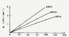
1) in acoustic emission detection, sensor and preamplifier has special importance. Because they decide the performance of the whole of the AE detection system signal-to-noise ratio, dynamic range, and the amount of information [3] in the AE detection, in addition to the special object, mainly working band in 100 kHz to 1 MHz. This system adopts the AE sensor and preamplifier is developed by us [4, 5]. Sensor has two kinds: one kind is broadband, in 50 kHz ~ 1 MHz band has a flat response) typical sensitivity curve as shown in figure 1), to obtain more abundant AE information, but slightly lower sensitivity. The other is a resonant AE sensor, the use of resonance peak near the high sensitivity of typical curve (as shown in figure 2), can significantly improve the receiving SNR, but information loss is also big. Experiments show that both kinds of sensors are able to receive the AE signal produced by rubbing, but consider from the waveform analysis, broadband sensor effect is better. Preamplifier from both noise (especially the work of 50 Hz frequency interference)
2) host system without using common multi-channel AE testing system parameters for characterizing the structure and the traditional threshold (events, ringing, counting, etc.) [2, 6], and adopted the new physical ideas and dedicated system. Through the analysis of the rubbing process research, we think at the beginning of the rubbing occurs, the rotor and the wall just in a local area contact, the rubbing inspire the AE signal is low frequency periodic speed signal (the scene is mostly 50 Hz) modulation, so you can pick up the AE signal envelope as the basic parameter detection. Simulation experiments also show that AE signal envelope is rubbing the sensitive parameters, with or without rubbing, receives the signal change significantly; Rubbing occurs, in the envelope signal with rotating speed frequency of the fundamental wave (and sometimes its higher harmonic components significantly increased. To do this to the system development has brought a series of advantages, not only improve the sensitivity and accuracy of fault diagnosis, and simplifies the complexity of the system, reduces the development costs. AE envelope not only retain the main information of rubbing process, but also can effectively suppress the interference of random noise. For example, big spike pulse is one of the generally is not easy to deal with the noise of the AE system, it has much effect on the ringing count, and by raising the threshold level to eliminate the very hard, but the envelope signal especially its fundamental frequency component is not sensitive to this. Another advantage is that the envelope and in effect at the time of the rubbing AE signals compared to low frequency signal, its subsequent processing and AD conversion process is much easier than it does the AE signal itself. In addition, similar dedicated system development is currently an important field of AE technology development, it is especially suitable for all kinds of industrial process of continuous monitoring and diagnosis of the field application of [7].
3) BUAA rubbing AE detector in addition to A and B % % AE signal receiving and processing of actual channel, and A used to provide the parameter % % C channel. The former provides 2 AE signals at the same time, you can also give A line of AE source location and time information, which position is identified. % C channel used to enter the rotor speed signals or other related. The rotor speed signal plays an important role in the rubbing test, it is the time domain and frequency domain analysis provides A reference signal. As the benchmark of time domain, can be used to channel A and B % strictly synchronous sampling cycle, avoid or reduce the signal Fourier transform (FFT) caused by non period truncation error, speed signal after FFT for the % of A and B signals in the frequency domain analysis has provided the fundamental wave and every harmonic frequency benchmark, for the purpose of rubbing the signal frequency domain identification. Also pointed out that introduced by C channel speed signals for system USES relevant technology enhancement and noise suppression provides convenient. It is generally believed that % % AE signal the occurrence of randomness, but under certain conditions can also be A quasi periodic signal. At the beginning of the rubbing occurred, the envelope signal relative to the rotating speed signal has A definite phase relation, thus the speed signal as reference signal, the envelope in time domain of collecting quantitative superposition, reinforce each other, the result is useful signal and noise is not related to each other, and tend to be offset. After m times the average received SNR is improved m [8].
2 instrument hardware and software
System hardware block diagram is shown in figure 3. A and B channel andadministrative and signal processing block diagram as shown in figure 4. Andadministrative db gain 60%, can be made of the attenuator adjust gain. Amplitude envelope detection, low-pass filtering and signal adjusted into the AD board. On the andadministrative board also has gain alarm circuit, its purpose is to get the right gain selection, make the AD transform has the best dynamic range.
AD board is controlled by single chip microcomputer [9], from A, B, C % % 3 channel signal after analog switch for the AD conversion, multichannel sampling using switch points. Due to the AD was conducted after the envelope detection, transformation of just 3 low frequency signals, so although the highest sampling rate per channel decreased with increasing the number of channels, but does not affect the work performance.
Digital signal after sampling spooled in AD board, data memory capacity of 4 x 32 k bytes. After sampling through interface board data in RAM into the host.
Test system software includes three parts: single chip microcomputer sampling, microcomputer pre-treatment and post-treatment procedures. Single chip microcomputer sampling program written in assembly language (figure 5), the content for the receiving host instructions; Report the host andadministrative board have alarm signal; No overflow, such as signal amplitude according to the sampling frequency, channels coming host combination parameters such as sampling, sample length, and the temporary data RAM; End of the sampling, RAM content through the interface into the computer memory. This part of the program solidified in the EPROM.
Microcomputer processing software before including the choice of sampling channel, frequency, length, sampling data of the fast Fourier transform (FFT), graphic display, the screen print data (sampling and spectrum), stored and read out data sampling and spectrum (), and to provide secondary development post-processing software (computer). For the convenience of use and maintenance, the part program adopts the multiple drop-down menu structure, most of the parameters can be made of the user through the menu options to choose.
Microcomputer post-processing software including time orientation, the superposition of the average time domain data, fault analysis and pattern recognition, and the other of secondary development by the user program.
Three experimental tests and results
Test includes both laboratory and field. Simulation experiment is conducted on oil film support the rotation of the bearing, the analog source adopts aluminum contactor and the axis of a slight touch, field experiments are done in a certain power plant unit maintenance. Simulation experimental results is good, the system works well, reached the predetermined target. Also achieved some results in site test, it remains to be further data accumulation.
A group of typical simulation results is given below. Figure 6 and figure 7 are respectively system collected before and after rubbing occurs the time domain and frequency domain waveform acoustic emission signal envelope diagram. Can be seen from the chart, rubbing occurs, the fundamental frequency signal in the envelope signal and speed synchronization characteristics significantly, and there are several times frequency components, it may related to the tips of the rubbing AE signal pulse shape.
Figure 6 without rubbing occurs in typical time domain signal and its spectrum envelope
Figure 7 rubbing occurs in typical time domain signal and its spectrum envelope
Rubbing ae testing system without the traditional acoustic emission characterization parameters and testing the main case, and the envelope signal and its spectrum analysis method was adopted. Theoretical and experimental analysis show that the technology used in large rotor rubbing test is feasible, especially in early fault diagnosis it is sensitive than others, and high cost performance, application prospect is a means of detection.


 Blog
Blog