In the process of cutting, cutting tool failure (mainly including grinding blunt, limb loss and the edge plastic deformation or burning blade) and the process of grinding wheel condition (such as grinding wheel contact with the workpiece, the grinding wheel dull and grinding wheel dressing control, etc.), to cut the normal grinding process has important influence, such as: failure cause machine periodically for machine tool knife interrupted cutting process; Grinding wheel drive into and workpiece feed speed control affect the grinding machine processing productivity. Industrial statistics to prove: tool failure is the primary factor of nc machine tool machining process interruption, it accounts for 22.4% of the total time machine downtime; Grinding wheel and workpiece contact control can improve the grinding efficiency by 10% ~ 30%. Since the 80 s, cutting tools, grinding wheel process monitoring and control technology and equipment research and development to the attention of the countries.
In order to ensure the machine (especially the nc machine tool) and expensive and the economy and safety of large workpiece processing, requirements for tool/grinding wheel the implementation of monitoring and control. Using cutting tool/grinding wheel after monitoring and control device, can avoid to cause 75% of machine downtime technology and the harm of human factors; Can effective use of the second part, three shifts and holiday time, make the machine utilization rate is greatly increased. Over the past 20 years, machine tools, CNC machine tools, in particular, take higher than traditional processing cutting dosage, make the "dangers" of cutting/grinding process is much bigger than the traditional machining process. And a lot of difficult processing materials widely used (to the early 80 s, this kind of engineering materials is accounted for 43% of total engineering material), the new cutting tool materials (coated cemented carbide, Al2O3 and Si3N4 ceramics, metal, ceramic, and cubic boron nitride (PCBN) and diamond, etc.) of application, increase the risk. To ensure the security of systems, equipment and workpieces, improve the utilization rate of machine tools and machining productivity and quality, reduce scrap rate and processing cost, reduce labor intensity, reduce energy and material consumption, must use the process of cutting tools and grinding wheel monitoring technology and devices. Practice of all countries has proven its effectiveness, safety, and use efficiency.
1. The cutting force/torque real-time monitoring system
(including the component of the cutting force and moment) of real-time detection value is one of the important parameters of dynamic cutting process optimization. At the same time, it represents the process of cutting tool, workpiece and the operation condition of the equipment status, is an important process parameters. Cutting theory research proved that the cutting force increases with the increase of tool wear, usually in tool breakage, cutting force and cutting torque transient drop jump. As a result, often indirect monitoring tool wear with cutting force or torque or limb loss, and use it to monitor the cutting process status, or cutting/grinding force optimization control. Process monitoring method based on cutting/grinding forces are:
L) determination of cutting force changes in quantity, monitoring tool wear and its sensitivity up to 50 (including m;
2) to determine the cutting force component ratio, the wear monitoring sensitivity up to 20 ~ 30 (including m;
3) determination of cutting force component of the power spectrum peak or peak amplitude, the wear monitoring sensitivity up to 20 ~ 30 (including m;
(4) using the miniaturization of liquid statics element MIH - Cell) determination of the axial force, side force and moment, its sensitivity is higher than the semiconductor strain gauge, the resolution is 4.5 ~ 11.2 V/N (20 ~ 50 V/lb).
Strain gauge, semiconductor strain gauge, piezoelectric force sensor, accelerometer and other deformation or load detector (such as the MIH - Cell) is a common force and torque sensor. In addition, there are also using the method of detecting motor drive current characterization of cutting force. They belong to the power/current measurement method.
Recognition method based on cutting force has a larger development, such as cutting force derivative method is developed, in order to feed the change of resistance of Fx derivative value symbol to judge the tool grinding blunt; Based on the differential value of the axial force and torque of comparative judgment small diameter cutter broken, with the integral and Cook equation discriminant wear; And using the FFT analysis of cutting force, according to the main peak in the change of amplitude and time condition is used to identify the tool breakage, and so on. This kind of tool monitors for supply. They are sensitive and convenient to use. But the main obstacle to its use is to determine the identification/judgment threshold, requirements in different cutting tool and the workpiece combination of conditions for data collection and analysis, to determine the alarm thresholds. Another difficulty is that the sensor is convenient installation problems remain to be solved.
(1) is characterized by cutting force principle of real-time parameters of cutting tool condition monitoring
1) cutting force derivative method: in-depth research proves that the feeding resistance Fx rate of time - a, the second derivative, a characterization of cutter blade wear after the average width of the VB function, namely the relative to the VB -t curve wear in the early stage, Fx characterization of VB change the ability of the poor; In normal wear stage, Fx showed no vibration area and its late micro wear with vibration area; Changes from normal wear and tear to sharp wear points in the second derivative is symbol of transition point, namely the normal wear stage, F "x (t) < 0; and from the beginning of the sharp wear stage, F" x (t) > 0. Therefore, as long as find Fx second derivative
Numerical symbols change, can determine the cutting tool into the sharp wear stage, if keep F "x (t) < 0, the normal wear stage, as shown in figure 1.
Under practical conditions, however, when the VB -t curve is not a typical relations, the three phases of the research results of characterization of poor performance. But in normal wear stage knife blade crack occurs, how to fix the above criteria, not reported.
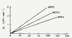
2) cutting force component ratio method: village of her love of Japanese scholars research proves that choosing Fx/Fz and FY/Fz for characteristic parameters can identify the tool wear VB value, namely when the VB increasing, Fx/Fz and FY/Fz two cutting force component ratio increase, so they can be indirect characterization of VB value changes. But, this kind of method is: the deficiency of the requirements in different tool workpiece combination and cutting condition changes to study to determine the cutting force component ratio and the relation between tool wear condition.
3) energy method: using the micro wear stage in the figure 2, the characteristics of Fx vibration phenomenon in a (t), with the change of energy characterization of the occurrence of fretting wear, can forecast tool wear limit is about to enter a sharp wear stage.
1 above) and 3) method can only be characterized tool wear transition point of problem, cannot achieve the real time measuring tool wear. For this, based on the 2) method, autocorrelation analysis was carried out on the feeding resistance, establish autocorrelation coefficient and the relationship between the VB value, in order to identify the wear value. But there are two contradictory unresolved: 1) how to realize the tool wear value of real-time calibration measurement? 2) how to calculate all wear criterion? In Czech j.t. luety and others on the basis of power spectral analysis, end milling cutter machining cast iron pieces of eight teeth (climb milling and inverse milling two ways) are studied, it is concluded that the power spectrum of cutting force in cutting tools, the characteristics of the damaged and undamaged after is shown in figure 2.
From figure known
1) 1, 2, the main frequency peak position, regardless of the tool breakage or not all the same, namely 1 peak at 300 hz, the second peak at 600 hz, but the cutting force spectrum amplitude change;
2) normal milling, 1 main peak amplitude is smaller than the tool breakage, 60% ~ 70% larger than the former, the latter 2 main peak amplitude normal is nearly three times larger than when the damage;
3) when the milling cutter breakage, 40 ~ 140 hz and 400 ~ 600 hz period of time on the peak.
This research leads to a kind of milling cutter breakage recognition method, which at times of peak frequency 40 ~ 140 hz and 400 ~ 140 hz, with difference as recognition parameters, cutting force in milling insert damage identification.
(2) based on the cutting force of drill grinding/breakage process monitoring system
Monitoring principle: 1) according to the results of experimental study, when choosing drilling bit axial T cutting force and cutting torque M as input characteristic parameters of bit wear/damage monitoring system, set up between them and drill grinding/damaged value model, criterion threshold is determined, according to this model can realize monitoring of drill grinding/damaged.
(1) the mathematical model of bit wear - Cook equation. When drilling bit of axial force for T, bit the knife of the average width of the wear after value of omega, according to drilling data can get the following regression equation (called Cook equation) :
T = 3.185 HBdf HBdr Hbd2 + 0.022 + 7.399 + 1.217 HBd omega (1)
Omega = (a + b) omega omega / 2 (2)
Type of T - bit axial force (N);
HB - brinell hardness of workpiece material;
D - bit diameter (mm);
F - when the drilling every turn feeding (mm/J;
R - bit blade radius (mm), typical values for r 80.01 mm material;
Omega - knife surface after the average bit wear width (mm);
Omega, omega b - feng (top), blade bit wear band width.
By type (1) can be obtained
Delta T ∝ delta omega (3)
T (2) when the drill bit broken, the axial force and torque M both instantaneous drops to zero.
(3) cutting experiment proved that the deep hole drilling and hole drilling method for the influence of the cutting force is small, can be neglected.
2) monitor system in figure 3 for the monitoring system diagram of bit wear and fracture. When spindle start idling, automatic balancer makes the output of the dynamic measuring instrument automatic zero adjustment. Wear monitoring mathematical model of the system for the Cook equation, as shown in type (1). Using the axial force of the detection system integrator of waveform. Drilling and bit wear for the first time, monitoring system to record the peak value of axial force Tm. In the process of bit wear, bit wear value and axial force in compliance to Cook equation, according to the first drilling bit wear and the measured value of axial force of incremental delta T1, + delta T1 (Tm) as the comparator input value. From the second time later in the process of drilling, when the output of the integrator value is greater than + delta T1 (Tm), the comparator 3 to wear discriminator level signal. If within 0.3 s time, continuous more than + delta T1 (Tm), was judged to be wear and tear, recognition results by crosslinking (connected) interface into machine tool NC system, or connected to the alarm display system, send out alarm instructions.
The system adopts two parallel differentiator T axial force and torque for parallel processing, in order to monitoring the wreck a bit at the same time. Comparator 1 to 2 set point is still set according to comparator 3 set method. When T and M differential value more than the input value, the monitoring system of identification subsystem to determine bit to wreck. Also, can and machine tool NC system and alarm system is linked together, send out alarm signal. The experimental results show that the system is the recognition of bit wear the success rate of 87.3%. Figure 4 is a Carno9ie - Mellon university in Pittsburgh design based on the drilling axial force testing of real-time bit fold (break) loss forecast system block diagram. The system is used for CNC drilling machine, the experiment with bit is ф 8.0 mm (MT high speed steel standard twist drill), processing 100 mm * 100 mm * 200 mm A1SI1045 steel, cutting dosage for. Cutting speed nu = 15 to 16 m/mim, feeding the f/r = 0.032 ~ 0.204 mm, according to the procedures of hole drilling, hole depth h = 24 ~ 25 mm, no cutting fluid for dry cutting. Piezoelectric ceramic type dynamic dynamometer is installed; On the workpiece, used to detect when drilling bit under axial force. Detection signal after charge amplifier amplification, A/D (modulus) conversion, then input in the computer. Through the digital input/output (I/O) interface and four relay connected. The first relay is to start the machine with engine, the second relay is closed for starting circuit and the third relay is closed to restart the circuit, the fourth relay is closed circuit. After three relays are respectively for machine start, stop, and feed movement stop and return. The system of signal sampling frequency is 500 hz, the wear identification model is still use type as shown in (1) Cook equation. Department TongGong bit wear and wreck a (bad) monitoring with sharply.
(3) turning cutting force figure 5 is based on the cutting force detection of real-time monitoring and control system of CNC lathe tool life monitoring system.
Tests showed that the research and monitoring system, based on cutting force/torque process of cutting tool condition monitoring system and the device has the following key technologies to be solved:
1) how to improve the sensitivity of the sensor;
2) how to determine the force/moment for guarantee high success rate of recognition threshold;
3) how to ensure access to power under the high speed signal;
4) dynamic dynamometer improvement, in order to adapt to the determination of low frequency power, improving the performance of its installation, to eliminate or reduce the effect of its dynamic rigidity of processing system.
2. The power/current monitoring system
It is a kind of use of the spindle motor and feed motor related variables, such as current, voltage, phase, power, etc.) and the tool wear and breakage or flutter conditions such as cutting process, realize the working condition of cutting tools and cutting process condition monitoring and control system. In addition, some monitoring system is the use of power in the conversion value measured cutting force or torque, then according to the force/torque and the cutting tool or grinding wheel and workpiece process conditions contact condition for identification. The latter is mainly used for roll grinding machine grinding wheel and workpiece contact monitoring. On the basis of the power/current monitoring/detecting device is the earliest research, development and application of monitoring system, the commercialization of its representative, device or instrument with the United States Cincinnati Mi1acron company of torque control monitoring device (TCM), Switzerland (SMT) cutting machine tool company monitors, etc. Because this kind of system with functions of low cost, easy to use, more advantages, such as for industrial and scientific attention and concern. The main deficiency is low sensitivity and detecting precision is vulnerable to the impact of machine tool thermal deformation. Aiming at these deficiencies, a lot of improvement.
(1) the spindle driver and feed motor measurable parameters related to motor parameters such as power and current. They are loading system, mechanical drive system (such as vice gear transmission, belt transmission, etc.) and control the current of the motor. The influence of such factors as In the process of cutting, measurable parameters of the motor depends on its type. For ac asynchronous motor, the following parameters can be determined, but they are influenced by load:
1) the input power P;
2) armature current (I);
3) current and voltage phase Angle phi;
4) slip s
S = (n1)/n1 (4)
Type in the n1 - synchronous speed;
N2 - motor speed.
5) the phase voltage U.
(2) measuring principle
: 1) integral power method for ac motor, its effective power P can be expressed as
(5)
Type in the U - voltage;
I - current;
The cycle of Tm - U and I.
(5) can be digitized
(6)
Type of N - sampling points in a cycle of Tm.
Uk and Ik mean is the product of the effective power of the motor.
2) power single-phase section method: at any time, at the same time to collect the three-phase instantaneous power of the motor, and this time the effective power of the motor. When the three-phase load balancing of the motor, its each phase voltage, electric current can be expressed as respectively
(7)
(8)
The instantaneous power of the motor for P = P Pa + Pb + Pc (9)
Using (7) and (8) solving type (9), the instantaneous power P expression
(10)
When the three-phase load balancing, P has nothing to do with T, therefore, under the assumption that, single-phase power characterization of motor power is available. This simplifies detection system, and achieve the same purpose. If take omega t = PI / 2 section, can be obtained
(11)
To make test results are accurate, can take a few more cross section, such as:
Um - phase voltage of the maximum;
Im - phase current maximum value;
Omega - angular frequency;
Phi - power factor;
T - time.
3) real-time transient power: it is the improvement of the above method, whose principle is: the instantaneous power P equal the sum of the instantaneous power, and each phase of the instantaneous power Pk (k = 1, 2, 3) can be the product of the instantaneous phase current and phase voltage U I expression and application of Hall effect sensor (Hall), its linear response frequency of 0 ~ 5 KHZ) to convert phase current into a voltage signal, use a negative phase shift voltage transformer voltage transform into corresponding voltage signal, and then put them into the rapid multiplication circuit (AD532, the distortion degree of < 1%), to calculate the instantaneous value of phase power in real time. For the three-phase ac motor, exist the following transient relationships:
(12)
(13)
(14)
The devices shall meet the following requirements: (1) there are on the band width of 0 ~ 2 KHZ response ability; (2) and the motor load on the current insulation; (3) have attenuation frequency device, to obtain signal on the identification of spectrum; (4) all of the current, voltage and power measurements are output terminals, available for analysis or recognition.
Using FFT analysis, looking for stable cutting and continuous turning and milling mode frequency characteristics under different cutting condition, found in the 118 Hz frequency component corresponding to the slip s, and 200 Hz characterization of cutting vibration, 39.45 Hz frequency corresponding to the power spectral density and tools. Using piezoelectric sensors to measure the force/torque (strain) and the main motor power or the feed motor current information logarithmic power spectrum analysis, found that the spindle motor power and torque with the current of feed motor has a good correlation.
4) current measurement: there is a certain type of tool condition monitor, such as the Swiss machine tool company (SMT) out of tool condition monitor (CFM), is based on the determination of motor current. Cutting force calculated by the measured current value (also can be X, Y, Z three directions component), build tool wear and breakage with the mathematical relationship between the current rate, as a recognition model. Input current sensor is used in the main motor or servo motor servo amplifier current as input. Current study of SMT, the feed force (expression) more sensitive than the main cutting force (current) to reflect the tool limb loss condition, such as increasing into four times to make the tool breakage, the main cutting force was only 25% increase. CFM system is to use the learning way of working. Record the current study, the control computer or reduced by the current values of cutting force, and set up the tool breakage, tool wear and maximum wear three threshold. It is suitable for rough machining tool monitoring, it is another command distinguishing rate was 0.5 ~ 0.7 kN, when cutting steel, for example, when the feed rate f = 0.3 mm/min, the cutting depth of alpha P = 1 mm, cutting force is 0.6 kN. Knife surface after cutting experiments show that the maximum wear and feed force (Fx) correlation coefficient is 0.93, the sword of the average width of the wear after the VB and feed force (Fx) the correlation coefficient of 0.85.
To sum up, for ac motor, the monitoring of cutting process can use some of the variable spectrum of the motor parameters, they are:
1) the power of the motor/current instantaneous value or average;
2) phase Angle between current and voltage;
3) to detect a certain power spectrum component of the frequency change, etc.
The measuring method are as follows:
1) method to measure current in parallel;
2) by magnetic flux detection current;
3) use ammeter or power meter measurement;
4) power meter is used to test power.
Sensing detecting motor, the corresponding parameter can successfully achieve the tool breakage detection. Sensing the servo feed motor current can be detecting tool wear. But when asked for current and the tool wear value was positively than relationships. For small diameter cutter, the current does not change significantly with the tool wear, this is the power/current method is not sensitive area. In addition, there are a lot of studies have shown that:
1) in the cutting tool wear or damage when, feed force increases more than the tangential force.
2) the variation of thermal distribution of machine tools and machine tool temperature influence on the motor current measurements is quite big, especially hot effect on feed drive current measured value is greater than in the spindle drive current.
(3) monitoring system of power monitoring system composition block diagram is shown in figure 6. It using the transformer structure detection sensor detecting motor input current, voltage and phase values, for simulating the measured value transformation, the detected analog signals of the rectifier for interface circuit can be accept. At the same time provide sampling benchmark sync signal. Through the interface circuit and computer interconnection.
Phase detection monitoring system as shown in figure 7. Detect the voltage and current signals by the plastic, then through the interface circuit and counter, output to the computer to recognize. When the computer recognition and should send out alarm, through the alarm unit issued a report to the police. The recognition program adopts the curing way a computer. The system has been used in large planer milling machine, its recognition success rate of 90% or more, identify the resolution is 1%.
3. The acoustic emission monitoring and control system in real time
The characteristics of acoustic emission (1) cutting process As mentioned earlier, the cutting process is under a certain energy consumption to maintain the nonequilibrium of time-varying dynamic process, it has the following features:
1) cutting process of acoustic emission detection sensor system to detect acoustic emission (AE) signals are low SNR signal, the amplitude frequency characteristics change. Due to the cutting process the cutting tool and the workpiece, chip and the rake face of time-varying friction, on the surface of the knife before and after wear, chip formation, fracture or coil workpiece, the cutting way (continuous and discontinuous cutting, milling and inverse milling, etc.) and the change of cutting condition and so on, almost all along with the cutting process and can cause the emission of AE wave mechanics phenomenon, when they are not monitored parameters, formation of noise. Combined with all kinds of machine, electricity, magnetic, acoustic interference, to detect the AE signal is low signal-to-noise ratio. At the same time, because of the blade material and grinding quality fluctuation, cutting condition changes, the workpiece material properties, such as the change of the AE signal caused by changes in the amplitude frequency characteristics within a certain range.
2) the fuzziness of signal recognition. AE sensors to detect the AE wave is repeatedly by the propagation, reflection, refraction and dispersion effect of the attenuation of AE wave distortion. Based on the AE wave response output is used to identify the conditions of the AE signal, often exist in the condition of dividing intermediary transitional, form the uncertainty on the partition, namely ambiguity.
3) strong interference of manufacturing. Mechanical processing workshop site there are many interference, such as all kinds of mechanical shock and vibration, background noise, gas-liquid system leakage, frequent start-stop of various electrical equipments, the power supply voltage and current fluctuation and so on. As a result, the scene of the machine, electric, magnetic, acoustic interference, especially the transient interference, they often drown or mixing characteristics of AE signals required for the identification, cause this kind of monitoring system of high rate of false positives, low precision, serious when, make the AE monitoring system cannot be continuous and stable to work.
Experiments confirmed that AE signal frequency band width, cutting process from a few hz to tens of megahertz. In order to consider the AE detection, signal processing and recognition system is practical and economical, cutting tool monitoring and control system often USES a few KHZ to AE signals within 2 MHZ band. Can approximate that AE signal from the normal cutting process is continuous AE signals, and the tool wear in sharp stage or the blade broken main type of aperiodic sudden AE signal. Compared two kinds of signals, the latter's level is often significantly larger than the former. Experimental determination, the processing of the workpiece such as steel, cast iron, a variety of hard alloy car, milling, boring cutter, Al2O3 base with Si3N4 ceramic knife abnormal wear and tear when the signal peak between (80 ~ 700 kHz), amplitude level is 0.5 ~ 7.5 V (when the value of 40 ~ 60 db), signal length is dozen microseconds to several milliseconds, and the sudden type characteristics of the cycle. Mechanical shock and vibration noise main peak frequency under 100 KHZ, electric installation interference noise peak frequency is above 1 MHZ.
(2) cutting process of cutting tool condition of fuzzy recognition Although, abnormal tool wear and breakage when the characteristic of the AE wave is an objective existence of physical phenomena. But as a result of these reasons, the detection of AE signals is change according to the condition. When AE characteristic signal is analyzed, it is difficult to use the frequency, amplitude, or ringing of AE signal waveform parameters of numerical and envelope detection strict distinct characteristic parameters such as the conventional threshold, to determine the actual working condition of the cutting tool. In other words, in pattern recognition, the AE signal and the signal processing of the data between the classification of information with the working condition of the continuous transition state, can not find a clear and certain characteristics of the interface. This phenomenon can be called a mediation transitional condition recognition. It is this characterization of AE signals of tool conditions and its processed data information exists between the intermediary transitional form class division in the intermediary transitional caused by uncertainty, fuzziness. The uncertainties of the ambiguity caused with random uncertainty has a qualitative difference. If not considering the fuzzy uncertainty, the results statistics show that by the ringing of numeration w identify the success rate of 60% ~ 80%, and by AE signal envelope detection peak Ap, to identify the success rate is 50% ~ 80%. Work to meet the practical requirements of accuracy, it is necessary to study how to improve the success rate of recognition. Therefore, should consider the fuzziness of the AE signal recognition, therefore cannot use precise mathematical or probability statistics method to describe the AE signals of cutting process characteristics.
Figure 8 expressed a kind of intelligent fuzzy identification system. It is based on a series of rules of recognition system. The system includes the signal processing of the AE signal discrete fuzzy input set, register set, knowledge base, fuzzy inference machine and output.
If the letters or Numbers under the symbol "~" said fuzzy number, fuzzy sets or fuzzy relations, said such as fuzzy Numbers, fuzzy set, and fuzzy relations. Figure 8 system input sets are included in the characterization of fuzzy input vector of cutting state or tool conditions.
The weight of fuzzy subset (I = 1, 2,..., n; j = 1, 2,..., m). The input of the system can include the fuzzy real Numbers, statistics, also can include discrete fuzzy subset, such as amplitude envelope detection: {greatly, Large, Medium and Small} or = {Huge, Large, Medium, Small}. Register the input with the adaptive processing of AE signal and other auxiliary information according to the supplementary rules development, such as AE signal envelope detection of peak and average. R rules set and knowledge base Dk completed by consulting and experience. Register can be real-time learning and inference according to predetermined rules. Rules of use "if... than..." The logical relation of statements. Corresponding to the membership function of input output conclusion mu (phi I) can be expressed as
(16)
After the lambda cut sets of a given output, monitoring yi for the conclusion of the function
(17)
From (17), lambda cut sets to make fuzzy output into a clear and definite conclusion.
(3) comprehensive monitoring acoustic emission tool system in figure 9 is the research and development in our country the MT - 8000 type of acoustic emission tool monitors the system block diagram. It outside using broadband AE sensors mounted and installed in the machine tool spindle end cover or housings, lathe tool rest, can finish cutting, end milling, boring, milling, drilling and maneuvering attack thread cutter real-time monitoring. AE signals detected by the amplifier, frequency selective filter, bandpass filter, fast detection and ringing count circuit, after further signal processing, through the interface circuit is connected to the computer. Under the control of the intelligent recognition system, a real-time tool abnormal wear and tear (or wreck) monitoring, once the computer recognize abnormal condition occurs, will send out the alarm instruction by alarm and display unit. At the same time, through the signal transmission interconnection device interface with NC machine tool system, completed by NC system for machine knife or starting out with process transformation, such as work instructions.
This kind of real-time monitoring system can be used for FMS line of vertical and horizontal machining center, CNC lathes and turning center, etc. It has a strong resistance to the machine, electricity, magnetic interference ability, can complete a variety of high precision, steady cutting tool condition real-time monitoring and control, is a kind of practical integrated monitors.
4. The machine vision surveillance system
Through sight, hearing, touch, smell and taste organs obtain information from the external environment, the brain processing and recognition and understanding the objective world. In the modern artificial intelligence technology, machine vision of humanoid visual occupies an important position. Since the 50 s of this century, it gained rapid development. Essentially, machine vision is a sequential outside world description and transformation process, it finally gives a watch scenery general description, the height of the machine vision for understanding of the objective environment. Therefore, machine vision cannot simply equate to image processing. The latter refers to the image to image transform, does not include the recognition of the environment object, research or manipulate.
People living in the three-dimensional space, and be able to understand and grasp it. Humanoid machine vision also must be able to understand the three dimensional space information. Human visual presents a two-dimensional image of the world into a two-dimensional image on the retina in the eye. The brain must be from a 2 d image, form a three-dimensional space model. Therefore, said to simulate the brain structure from 2 d image, and understand the three dimensional world model for machine vision or computer vision, also called image understanding. Machine vision in the intelligent robot, manufacturing process monitoring and control have broad application prospects.
(1) visual information machine vision system include within the scope of vision brightness, color and distance, etc. The human eye vision system includes photoelectric conversion system, part of the retina, the optical system (focus and the regulation system of grating), eye movement system (including horizontal, vertical and rotational movements), information processing system (from the retina to the brain's nervous system). Machine vision system of the hardware system is shown in figure 10. The camera has two kinds. One kind is industrial video Camera (Vidicon Camera), it is composed of the tube and the corresponding electronic chart, its output as the standard of television signals. The scope of its spectral sensitivity in 300 ~ 700 nm wavelength, the light is emitted scenery focus on light sensitive target, form the image, by scan electron beam to the target, transform the image into a serial of electrical signals. Light sensitive target, electron gun and electrode in the camera of the vacuum tube, so the video camera volume is larger, and fragile and afraid of earthquakes, there will be time to drift when electron beam deflection. In addition, its service life and average trouble-free working time is shorter. The second Camera is Solid State Camera (Solid - State Camera), is the representative of charge-coupled device (CCD) Camera. It has one dimensional linear CCD or two-dimensional array CCD. The CCD is a set of discrete light sensitive element array. When light on its, each light sensitive element is proportional to the illumination of the charge. These charges gathered in each of the components of capacitor, array light sensitive element, using two-phase clock pulse charge in order to transmit to the input end of the amplifier. Amplifier output signal characterization of the voltage sequence images. The CCD spectral sensitive wavelength range is 420 ~ 1100 nm. CCD camera has a small volume, light weight, shock resistance, long service life, good reliability, electron beam deflection drift and yuan internal high pressure, etc. In addition, the CCD camera power consumption, less generally start in a few milliwatts. But its main drawback is photosensitive element sensitivity inconsistencies can be as high as 10%. Although you can individually correction pixel sensitivity, but more cost computer machine. It is generally believed that the CCD camera is more suitable for the application of machine vision system. Machine vision in accordance with the standard form of TV, in addition to the specific industrial camera, pixels are not square, but is a rectangle. Note this feature, otherwise it will lead to identify or positioning error, and even making it difficult to identify or locate.
The input image by A/D converter into digital quantity, transform into digital images. Usually, machine vision of an image is divided into 1024 x l024, 512 by 512, its the brightness of each point using 8-bit binary representation of 256 gray level. The distance of image information can be obtained through the distance meter with a color filter for color information, the information to the image processor and finish data processing and feature extraction. Often use computer to complete image processing. In real-time image monitoring and control, a high-speed image processor instead of multi-purpose development of computer image processing, to shorten the processing time. Such as using dedicated processor to calculate the image edge of local treatment. Common LISP to complete the analysis of image characteristics and calculate the object types and location relationships. In order to adapt to the dynamic observation, the machine vision system should have the following abilities:
1) to adapt to the changes observed object distance focusing ability;
2) according to the brightness adjusting aperture ability;
3) adjust magnification ability;
4) ability to rotate or move the selection field.
(2) the process monitoring using machine vision system in the manufacturing process monitoring, machine vision system is mainly used for:
1) to zero (work) monitoring of installation position, fittings card validity;
2) material transmission accuracy of location and material handling with the monitoring of machine tool interference;
3) the accuracy of cutting tool selection and wear monitoring;
4) manufacturing unit or system security monitoring and running state monitoring;
5) quality assurance system monitoring, etc.
Using machine vision monitoring tool wear/breakage has the following advantages:
1) for measurement of flexible, can adapt to a variety of tools and a variety of specifications of the blade monitoring;
2) can be compared with the new knife, obtain absolute grinding/damaged value;
3) measurement of high resolution, can be up to 10 microns or higher level;
4) is a non-destructive testing.
The main deficiency is:
L) it is difficult to make real-time monitoring;
2) the higher requirements to the site environment light field.
Figure 11 is the use of the tool wear monitoring system diagram of machine vision. Under test tool (or blades) installed in microscope worktable, is a precision fixture positioning clamping, to ensure the consistency of multiple installation measured values. Using fiber optic light beam on the surface to be tested. Microscope using 12 x zoom optical system, the eyepiece end installed 488 x 380 pixel resolution solid camera CCD. The output is connected to the benchmark regulator (corrector), to eliminate out of sync with image analysis system. Image analysis system adopts high performance image processing and computer systems. Computer system containing image processing instructions and tool wear analysis software. Blade wear before and after the system identification of maximum repeatability error is 4.2% ~ 7.8%.
.5. Cutting area noise monitoring system
Usually the acoustic emission method, cutting area noise method, ultrasonic detection and laser acoustic vibration teaching called acoustic vibration analysis, is the physical basis of physics. Mainly introduces the monitoring system of noise analysis below.
(1) cutting area noise analysis principle It comes from imitating the operator according to the acoustic signal monitoring working condition of machine tool and the method of cutting tool condition is put forward, its is based on speech recognition technology. It using microphone as a sensor to collect the cutting noise signal. Microphone without contact in is apart from the cutting tool on the distance. The noise of the microphone output electric signal after such as frequency selective filtering processing, speech recognition technology is utilized to extract characteristic information. Once established characteristic parameters and the relationship of cutting state, can make real-time identification.
(2) process and the operation of the machine tool cutting tool condition monitoring noise experienced operator can rely on his own hearing, can not only determine whether the machine has to start or stop, spindle running? The workbench movement? In the cutting tool? Tool change in motion? ...... Of a noise, but also from the cutting zone identification in cutting process is normal? Dull or damaged, wreck a tool? Even can determine what is ongoing process, and so on. Starting from the fact that, in imitation of a person hearing and the noise recognition of the brain, cutting area noise identification monitoring method is produced.
Noise when the machine running and cutting, cutting area contains a variety of machine tool operation status and the information of the tool condition, can take advantage of the multimodal pattern recognition technology to correct recognition. But to the reliability of the monitoring, cutting area noise monitoring system has the following characteristics:
1) to avoid the influence of people talking, not as a noise signal processing using human language frequency band;
2) using the spectrum analysis technology for cutting process the acoustic mode under various working conditions;
3) using cheap and reliable hardware system.
(3) sound monitoring system figure 12 represents a kind of vertical machining center with the noise of the monitoring system. The system consists of sensor noise cutting zone of microphone, acoustic signal pretreatment and recognition units, judgment, expect sound sequence generator, NC database and output units. System of the sampling frequency is 160 ~ 5000 hz, the sampling interval is 100 mu s, sampling points to 256. The system based on cutting experiments, the offline analysis to establish 62 standard mode, deposited in the database for real-time identification. The establishment of the sound system model for the vertical machining center of vertical milling, drilling and milling process different tool workpiece combination and different cutting dosage, the scene the working procedure and under the condition of different combination machine tool start-stop, normal working condition of cutting, tool breakage or abnormal noise signal. It can finish the process identification and tool condition identification. The cycle time of the system monitoring for 1 s, in the applications of vertical machining center to identify the success rate is 80% ~ 90%. At CIRP, the study is considered by experts can be practical, has the application prospect of process monitoring technology and devices.
6. Grinding wheel touches - monitor/tools
Traditional monitoring and control of grinding wheel and workpiece contact by the operator according to the real-time acquisition of visual, auditory or hand sensory information, done manually grinding wheel lateral work fast feed to feed conversion (table), or by the transverse feeding device, open loop control system to achieve this transformation. The former mainly depends on the operator's experience and skill, which relies on a preset schedule, that is before the grinding wheel and workpiece real contact to set aside a worker into idle. But the practice has proved that reduce or eliminate the empty process can improve the grinding productivity by 10% ~ 30%. At the same time, if can real-time detection grinding wheel a workpiece contact information, can also reduce the manufacturing cost, ensure the safety of machine tool equipment, artifacts, and the operator to realize automatic grinding cycle control and the automatically assigned the number of feeding. To reduce or eliminate work into idle method are:
1) used in the machine installation of the meter direct detection is processing size, control grinding head without idle grinding;
2) use of contact resistance, inductance, capacitance, eddy current and magnetic flux sensor testing contactor signal of grinding wheel and workpiece, empty grinding is realized;
3) the use of force/torque, power, vibration sensors such as grinding wheel/workpiece contact signal, realize idle elimination;
4) using lasers and other light visual method, close to or contact sensing method implementation process to eliminate or reduce the empty;
5) using AE sensor detection/contact information of the cup grinding wheel, for no work into idle grinding.
Nearly 10 years of research and application practice proved that acoustic emission (AD method can well satisfy the requirement of the grinding wheel, workpiece contact detection. The characteristics of AE method is the grinding wheel and workpiece contact instantaneous response is fast, sensitive and easy to use. The experimental results show that the force force method to detect signals than AE method to detect the AE response time lag tens of milliseconds, and AE signals than force sensitive. Current/power law than AE signal response time lag of 0.8 s, and a lower sensitivity (the present technical level is that when exposed to changes in power signal caused by less than 1% of the grinding wheel rotation, the total power can't perceive). Since the 80 s, countries in AE monitoring method and the device research and development, such as Italy's omar E20 grinder of the Persian company contact type tester, Chinese MJ acoustic emission monitoring instrument, etc.
(1) contact acoustic emission monitoring principle
1) using the grinding wheel and workpiece contact instantly the Kaiser effect of acoustic emission phenomenon, namely using the AE signal a significant moment step features for identification.
2) due to the grinding wheel and workpiece contact moments of AE signal rapid response ability, can be achieved within 0.3 ms response, contact resolution 2 microns or less, so the method can accurately realize contact monitoring.
3) contact detection using the grinding wheel and workpiece contact when the excision procedure or solid physical contact in the process of acoustic emission (AE) is high precision AE sensors (such as China's patent AE - 01) on the wide band and high precision of AE sensor detection to obtain contact data signal, on the regulation characteristics of spectrum of AE signal, which can identify and take effective anti-interference measures to improve the accuracy of contact identification.
4) use of interconnection interface can realize the control of grinding wheel in contact with the workpiece.
(2) the MJ type acoustic emission with monitor figure 13 is MJ type acoustic emission with monitor system block diagram. It by AE - 01 type high precision acoustic emission sensor for 1.5 MHz) or less (frequency response range, preamplifier, high cut-off frequency is 100 KHZ, attenuation slope to 18 db/OCT), main amplifier, bandpass filter, image detectors, recognizer, display alarm unit and the interface with NC system interconnection. Verified by industrial test and application of the monitoring instrument is confirmed that the grinding wheel and workpiece contact gap delta in 5-10 mu m < delta < 0, limited in 100 times the alarm, the success rate of 100%, the number of sampling response time of 0.3 ms or less, and can interconnect with grinder NC system, complete wheel - the workpiece automatic monitoring control loop. Application proves that it can improve the grinding productivity by 10% ~ 30%.
7. Cutting process temperature monitoring system
Cutting process, with the increase of tool wear, the knife surface and the workpiece contact area also increased, cutting friction intensified, the cutting temperatures rise. Cutting temperature and tool wear q has certain correlation. It is the use of the physical basis of cutting temperature monitoring tool wear.
(1) cutting temperature detection method
1) thermocouple method: cutting, cutting tool and the workpiece contact form a thermocouple. But this natural thermocouple characterization of temperature is not suitable for the monitoring of tool wear. Reason is composed of cutter and workpiece natural thermocouple measured temperature value and the relationship between the cutter blade wear width after is very complex, and sometimes show irregular state. Root causes of this situation are: (1) temperature is measured by the cutting tool and workpiece contact zone average temperature of each contact point increase in tool wear, the contact area at the same time also will increase, sometimes make the average temperature of the thermocouple measuring worse instead; (2) with different sets of cutting tool and workpiece, the cutting condition of all the thermocouple changing, complicate its relationship with VB. (3) the use of conductive ceramic knife when cutting tool will not form the natural thermocouple, and as a result of the cooling lubricant used often damage the relationship between the temperature and tool wear.
Therefore, multi-purpose artificial thermocouple thermocouple method. At a certain distance away from the blade preset small thermocouple, cutting process it has been applied to the determination of thermoelectric emfs, can eliminate the disadvantage of the natural thermocouple;
2) thermoelectric emf method: it is a direct measurement using artificial thermocouple thermoelectric emfs (mV) near the blade, set between thermoelectric emf and the tool wear value through the experiment of mathematical model. According to this model, can be implemented based on the tool wear monitoring of cutting temperature (thermoelectric emfs). But in the monitor signal processing, the main difficulty is how to eliminate chip (filter) chip deformation and volume of thermoelectric emf signal noise.
3) infrared method: using infrared detection system made by the blade of the infrared radiation, the signal represents the average temperature of cutting zone. The response speed of the infrared method and sensitivity were higher than the above two methods. But the actual cutting cutting fluid and the influence of the chip is often the difficulties of infrared detection.
Research proves that the monitoring of cutting temperature monitoring technology is an important process.
Figure 14 (2) monitoring system is a kind of lathe thermoelectric emf monitoring detection system. It consists of four claws, insulation of the spindle, cutting tool and workpiece thermocouple circuit, the input signal is entered into the measurement circuit amplifier 5 6, again into the fast Fourier transform (FFT) analyzer 7. When there is chatter vibration cutting process, the power spectral density curve and its peak value will change. This feature can be used to monitor the abnormal vibration of cutting process.
To sum up, in the process of cutting tool monitoring, industry and technology comparison is the consensus of opinion: AE method can implement high precision and reliable tool broken/wreck a real-time monitoring and control, and long-term research and development process of tool wear monitoring method and system can't to achieve high precision and reliable. Since the late 80 s, the rise in the cutting tool wear monitoring sensor fusion recognition. The study by using acoustic emission, temperature and vibration or other sensor fusion recognition wear and its experimental results achieve high alarm success rate 97% ~ 99%. Commercially available but there is a distance.


 Blog
Blog