Wind-power blades pick to: in order to implement the structural health monitoring of the typical characteristics of acoustic emission source analysis and accurate positioning, wind-power blades with glass fiber reinforced unidirectional composite material and multilayer composite material as the research object, USES the phi 0.5 mm lead to simulate acoustic emission source, explore the acoustic emission wave propagation in composite materials, the attenuation characteristics and localization precision. The experiment results show that the sheep composite vertical and horizontal transmission of acoustic emission and the attenuation characteristics are obviously different, longitudinal acoustic this big, small attenuation; Wind-power blades precise localization of acoustic emission source in field detection, the structure of the composite materials must be taken into account comprehensively and acoustic properties.
Glass fiber reinforced composite material than strength, high modulus, good fatigue resistance performance, widely used in the manufacture of wind-power blades composite structure. Influenced by random factors such as manufacturing, wind-power blades will inevitably produce fiber fracture, such as lack of glue and layered structure defects, these defects in the actual static/dynamic load, fatigue condition, wind-power blades will intensify structural damage accumulation and instability of damage, therefore, wind-power blades FRP composite material structural health monitoring plays an important role in wind-power blades to ensure long-term reliable operation.
Acoustic emission testing technology is sensitive to dynamic lack of land, can do real time monitoring, which can effectively reflect the failure process of fiber reinforced composite material damage, in recent years, foreign scholars have conducted related acoustic emission technique in the early days of the wind vane damage prediction and structural health monitoring research. Domestic research in this field in the initial stage, mainly including wind power blade crack acoustic emission monitoring and asked the idea of structural health monitoring. But for wind blade FRP composite material and the positioning of the acoustic emission attenuation research involves less. Wind-power blades based on unidirectional composite material and multilayer composite material as the research object, USES the phi 0.5 mm lead to simulate acoustic emission source, for acoustic emission wave propagation and attenuation law in composite materials and source localization features, for wind-power blades composite material provided a reference for the health monitoring of structures.
1 the experiment process
Experiment wind-power blades used in unidirectional composite material composed of unidirectional glass fiber epoxy presoak (brand for G15000) on the flat die after 60 layer, inside the oven heating pressure curing, the composite material layer plate thickness to 6 mm. In wind-power blades cutting of multilayer composite material specimen average thickness of 24 mm. In the process of the experiment, to phi 0.5 mm lead to simulate acoustic emission source, using AMSY - 5 full waveform acoustic emission instrument for real-time monitoring and recording acoustic emission signal. Acoustic emission monitoring using 3 ~ 4 100 ~ 900 kHz wideband transducer, built-in preamplifier is 40 dB gain, center frequency of 150 kHz, sampling frequency for 10 MHz, signal collection and read a value for 46 dB. The unidirectional composite material attenuation and sound velocity measurement, the four sensors alignment, longitudinal spacing are 60 mm, lateral spacing are 40 mm, simulation of the acoustic emission source from the center of recent sensor distance of 20 mm. The multilayer composite material attenuation and sound velocity measurement, the three sensor alignment, spacing of 60 mm, simulation of the acoustic emission source from the center of recent sensor distance of 20 mm. The positioning measurement, four sensors short form layout, unidirectional composite material spacing is 100 mm and 80 mm, multi-layer composite spacing is 95 mm and 55 mm. The acoustic emission monitoring process, use vaseline coupling between sensor and test board.
2 the results and discussion
2.1 unidirectional composite material attenuation with the source location
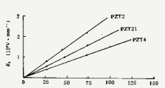
Wind-power blades unidirectional composites ae amplitude attenuation is shown in figure 1, both longitudinal and transverse attenuation through the three effective simulation of acoustic emission source according to reach the size of the four sensors to obtain.
The experimental results show that the three simulation ae signal amplitude attenuation, can effectively represent the unidirectional composite material longitudinal and transverse attenuation characteristics of acoustic emission; Longitudinal attenuation for o. 58 ~ 1. 6 dB/cm, lateral attenuation is 2. 4 ~ 4 dB/cm. Visible, unidirectional composites ae transverse significantly higher than the longitudinal decay the phenomenon stems mainly from unidirectional composite material structure characteristics. Wind-power blades in unidirectional composite fibers are vertically, sound waves in the main along the fiber direction of vertical transmission in composite materials, the attenuation is relatively small; And along the lateral composite materials, resin and fiber appear alternately, sound waves follow the circulation process of resin - fibre - resin seenlots of resin and fiber interface reflection, scattering and absorption, resulting in energy in composite transverse have larger ae amplitude attenuation.
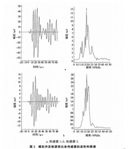
Broken lead to simulate the acoustic emission source reach the waveform and spectrum of each sensor is shown in figure 2, the waveform of sensors and frequency change is not big, not present ae wave dispersion effect. On the basis of acoustic emission wave arrival time difference of each sensor and sensor spacing, can calculate the noise emission in the propagation speed of unidirectional composites.
Wind-power blades by calculation, unidirectional composite longitudinal sound velocity of about 4640 m/s transverse velocity of about 1, 835 m/s. Visible, acoustic emission wave in unidirectional composites in the longitudinal velocity significantly higher than the transverse velocity. Propagation velocity of sound waves in material is mainly associated with the elastic modulus and density of medium, the higher the ratio of the elastic modulus and density, wave velocity is higher. Also the density of glass fiber and resin matrix were similar, but the elastic modulus of glass fiber significantly higher than that of resin matrix, it shows that acoustic emission wave propagation velocity is larger in the glass fiber, vertical transmission of sound waves in composite materials is performed along the fiber direction. Acoustic emission wave propagation velocity in the resin matrix is relatively small, and lateral spreading, sound waves in resin and fiber interface multiple reflection and extended the path, cause lower transverse propagation velocity of sound. In wind-power blades ae source location shall be fully considered in the unidirectional composite material differences in longitudinal and transverse velocity of sound.
At the scene of the wind power blade structural health monitoring, sensor general arrangement in the leaf surface. To obtain the location of the acoustic emission source, should be used in acoustic sensor array to achieve a two-dimensional plane positioning. The known acoustic speed in wind-power blades composites, each sensor can be based on the acoustic emission signal reaches the lag, calculate the precise location of noise source. This paper adopts four sensors, take the speed of sound for 3, 300 m/s. Combining AMSY wind-power blades - 5 system unidirectional composites ae source location experiment result is shown in figure 3.
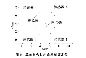
Experimental results show that the acoustic emission location source can basically reflect the simulated acoustic emission source location, but also exist certain error. This is due to the longitudinal and transverse velocity difference is bigger, unidirectional composite material with single sonic time difference positioning method cannot effectively obtain precise positioning of the source. In the field test of wind-power blades, according to the characteristics of wind-power blades composite material structure, the orientation of jet lag and regional comprehensive analysis, for ae source location.
2.2 multi-layer composite attenuation and positioning
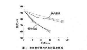
By simulating the range of the acoustic emission source, in turn, to reach three sensors, get multilayer composites ae amplitude attenuation as shown in figure 4.
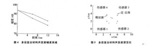
The experimental results show that the acoustic emission signal amplitude attenuation of 1 ~ 1. 16 dB/cm, on the basis of acoustic emission wave arrival time difference of each sensor and sensor spacing, calculate the wind-power blades multilayer composite sound velocity is about 4 273 m/s, and vertical unidirectional composite material properties.
Formed on the basis of four sensors rectangular array, in combination with AMSY - 5 system positioning method based on wavelet, wind-power blades for multilayer composites ae source location experiment result is shown in figure 5. Acoustic emission location source can well match the location of the simulated acoustic emission source, the closer to the middle area, more accurate positioning, the positioning accuracy is higher than the unidirectional composites ae source location. For the realization of the wind vane crack typical acoustic emission source such as precise positioning, should give full consideration to the structure of the composite material characteristics, and through the simulation experiments to verify.
3 conclusion
1) wind-power blades unidirectional composites ae transverse is significantly higher than the longitudinal decay, significantly lower than the longitudinal and lateral sound velocity.
2) the center frequency of 150 kHz acoustic emission sensors, the sharpest decline up to 4 dB/cm. To avoid amplitude attenuation too rapidly, in the field test of wind-power blades, the low frequency acoustic emission sensors should be adopted for ae source location.
3) wind-power blades multilayer composite material source of acoustic emission location can well match the location of the simulated acoustic emission source, the closer to the middle area, more accurate positioning.


 Blog
Blog