Cutting process sensing detection is aimed at optimizing the productivity of cutting process, manufacturing costs, or (metal) material removal rate, etc. The goal of cutting process sensing detection with the cutting force of cutting process and its change process, cutting chatter vibration and tool when contact with the workpiece and cutting chip state and cutting process identification, etc., and the most important sensor parameters have a cutting process of cutting force, cutting vibration, acoustic emission, cutting process of the motor power, etc. To run the machine, the main sensor to detect target are driving system, bearing and rotating system, monitoring and control of temperature and security, such as its sensing parameters have downtime of the machine tool, work piece's surface roughness and machining accuracy, power, cooling and lubrication state of machine tool and the flow of fluid, etc.
1. The cutting process technology
(1) the detection of cutting force of cutting force is the most commonly used evaluation processing conditions and cutting process technology parameter, and adaptive control system commonly used sensor parameters. According to the cutting force signal, can indirectly determine processing load, cutting chatter vibration and cutting/grinding process tool/wheel failure conditions (such as breakage or wear).
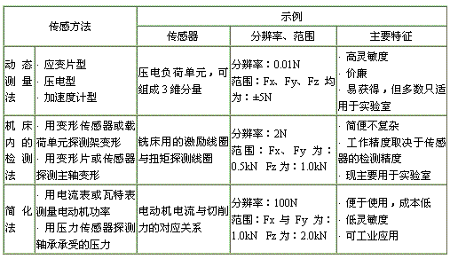
The probe is real_time detection of cutting force of cutting force along with the change of time (or cutting process). The main sensor dynamic dynamometer, strain gauge, or a variety of force sensor, its main features are: dynamic dynamometer although reliable and very sensitive, but often difficult to practical and more used in the experiment system; Strain gauge is suitable for field application, but not enough is easy to install, although can through the power and torque of the cutting force detection sensor signals calculated values, but this kind of method has low detection sensitivity, delay time long shortcomings. Cutting force sensing methods are shown in table 1. In addition, there is a kind of fluid statics based on miniaturization of components (MIH - Cell) of force and torque measuring device. It is by no existing compressible gas seal of metal containers, its sensitivity is higher than the semiconductor strain gauge, the resolution is 4.5 ~ 11.25 V/N (20 ~ 50 V/lb). It can be installed in the machine tool spindle or screw parts, can be on a table or special tool rest outside.
The sensing method of cutting force in table 1
(2) cutting chatter vibration detection sensor chatter vibration phenomenon and most associated with the dynamic instability of the grinding process, can often due to the vibration of tool/grinding wheel and workpiece subsystem. It appears to reduce the quality of the work piece has been processed surface, especially make the surface roughness increases, limits the production efficiency of machine tool, and potentially lead to tighten loose link and caused the accident. In addition, it also make tooling/wheel failure (wear and tear) to speed up.
Its sensing method can be divided into two types: direct method and indirect method. Direct method can directly determine the vibration of the machine tool, can also from a quiver in the change of cutting force when earthquake; The indirect method is through the sensor to detect seismic along with the effect of indirect characterization of chatter vibration, are shown in table 2. Vibration sensors can be set on a table or on the tool carrier. Dynamic measuring instrument has already been used in milling machine and lathe processing. Due to chatter vibration frequency often amounting to more than hundreds of hz so its response frequency is 800 hz, often feel enough. To this end, more than 2000 hz frequency response is developed in a new type of dynamic measuring instrument. Using the strain gauge sensor, the vibration signal is often the strain gauge load of machine tool spindle parts inside. In the late 80 s the development of thermoelectric emfs chatter vibration detection sensor method is to use the tool with machine tools (lathe) other parts of the insulation artifacts form closed circuit, using the principle of thermocouple sensor detection between tool and workpiece. When cutting chatter vibration appeared, contact area and contact pressure between the tool and the workpiece has great change, causes the change of the thermoelectric emfs. After FFT analysis of thermoelectric power spectral density can be obtained. Test confirmed that the corresponding power spectrum peak appeared in 10 hz, characterization of chatter vibration appeared. This method is of low cost, easy to operate, but the cutting parameters and the study of interactions between knife/workpiece materials still need further development. Indirect is often based on vibration marks, cracks or partial surface irregularities, such as information sensing detection to indirectly detect the occurrence of cutting chatter vibration. Therefore, common optical methods to sensing, such as using laser scanning system for grinding surface vibration mark and local irregular phenomenon, but its practicability is poorer. In addition, has also developed a way to use noise vibration (microphone) sensing chatter vibration method, and the noise level of the peak interval model is established, can predict chatter vibration. But it still need to further verify the reliability of various cutting conditions.
Table 2 chatter vibration sensing method

(3) the chip status detection sensor In the manufacture of high speed and ultra_high speed machining and automation, the condition of chip monitoring is a very important thing. Because it directly affect the process of the machined surface, security, and has the quality of the, so has become a very active field of research and development, put forward two main sensor detection:
1) using radiation pyrometer sensing chip state of a tool, using the average cutting temperature measurement to identify the state of the chip. But because it is more expensive, it is confined to the field of study.
2) using acoustic emission sensor dynamic measuring instrument or cutting tool, cutting tool/workpiece thermocouple sensor method of spectrum analysis technology to detect the state of the chip. This kind of method is the key to success is the sensitivity and reliability of the sensor and the signal processing, feature extraction and recognition of the law. While in the experimental study has been to identify ribbon chip, chip volume and devolop tumor, but more efforts to become an industrial application technology.
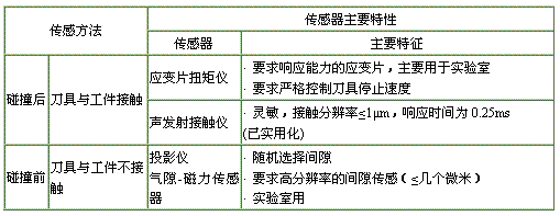
(4) cutting tools - artifact collision sensor For advanced manufacturing technology, to improve the efficiency of machine tool processing, often for higher feed rate, especially in the air knife should try to speed up the feed. Therefore, cutting tool and workpiece collisions become important monitoring content. Sensing of cutting tool - artifact collision usually divided into two categories, namely before the collision detection and collision detection method, as shown in table 3 collision detection method is to use of strain gauge installed on the machine tool spindle torque sensor for sensing signal after the collision, so that in the event of a serious collision before failure found slight collision between the tool/workpiece, thus the detection must be sensitive and reliable. Existing research shows that the acoustic emission sensor is sensitive and reliable contact, and a real_time strong sensing test, has entered the stage of industrial application and widely used in grinding. Before the collision detection is in front of the cutter and workpiece approach to physical contact detection sensor. One of the best sensing method is air gap - magnetic sensor. The drive coil, receiving coils are installed in the spindle box body and the tool on both sides, when the distance between the cutting tool - artifacts change caused by the change of the magnetic field lines, the corresponding clearance values of magnetic induction intensity is stronger, and according to the preset threshold signal change of feed rate control. This kind of magnetic sensor is influenced by the workpiece material.
Table 3 knives - artifact collision sensor
(5) cutting process identification sensor Recognition is a cutting process is rich with concepts. Modern manufacturing technology requires identifying cutting process, in order to the nature of the cutting process, modeling and simulation research to provide reliable real_time information; The control of cutting process and cutting tool geometry parameter, state of tool failure and artifacts, such as to provide information, so that grinding and cutting process optimization. Today, with acoustic emission sensor and the dynamic measuring instrument and luminous method is given priority to, also cooperate with the current/power, force/torque and the cutting temperature sensing method. Although many studies have demonstrated that AE method is preferred, but because of the complexity of the cutting process to identify and multi_objective, often using multi_sensor single target fusion sensor and multi_sensor multi_target sensing method, they have become most popular field sensing technology and monitoring technology, but this aspect research work is both more and widely. It will be in the making of the development of science, in the virtual manufacturing (VM) and virtual reality (VRM) development and manufacturing process monitoring and control in the research and development of rapid development.
2. The machine operation process technology
Working accuracy of machine tools for machining precision and machining quality has important influence. Force effect, heating effect and dynamic error of machine tool movement system such as precision and dynamic characteristics of machine tools have a significant impact. So, the operation of the monitoring and control of machine tool and process. To this end, often requires the following three kinds of sensor.
Detection sensor (1) drive system In order to realize the displacement of the drive system of nc machine tools (linear displacement and angular displacement) monitoring, and provides the deviating from the target value of feedback signal, often use a variety of sensors to complete information acquisition task. Laser interferometer, rotating transformer, such as line scale and main characteristics of displacement sensor are shown in table 4. Example: thread grinding machine automatic correction system, the sensor is made of the dual-frequency laser interferometer system linear displacement sensor and by its digital sensors and optical gain of encoder Angle. The resolution of the system can achieve 0.5 u m or higher.
Displacement (table 4) sensor
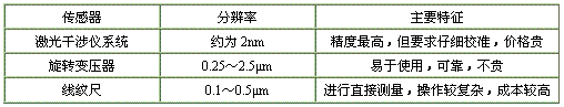
In order to obtain precision parts, requested the terminal output of driving system and the theory deviates from the value of the target as a feedback signal, so that to feedback control precision. In this kind of machining precision feedback control (also called precision compensation or correction), the amount of sensor position resolution is important. Laser jamming system is often used as the displacement error feedback sensor (buy). Industrial practice has proved that using this kind of high resolution sensor system can reduce machining error of 9/10. But due to the interference measurement to the strict requirement of the environmental conditions, its industrial application scope is small.
(2) the main shaft and the rotary system of detection sensor Main shaft bearing and the rotating error of spindle assembly of workpiece roundness has a great influence. The spindle system adopts an advanced rotary encoder precision of the spindle rotation error, can achieve nano_scale resolution sensor detection, its computer compensation system can control the spindle deviation under 0.05 microns. But the system is more expensive. At three o 'clock in the early 80 s contact roundness and cylindricity detection sensing method has large size parts in our country, the roundness and cylindricity processing measurement applications. It is measuring method in large inductance sensor and three typical applications in precision parts processing.
Due to the thermal deformation will change spindle pre_tightening condition. In the roller bearing system, the problem is particularly acute. Therefore, based on the strain gauge and acoustic emission sensor temperature compensation system to monitor and control.
In main shaft and the rotary parts monitoring, also use the following detection sensor: inductive sensor for detection of monitoring deformation of bearing or eddy current sensors, monitoring, chuck clamping condition of load cell sensor, gear online monitoring system of Angle sensor, monitoring the spindle rotation error of oscilloscope monitoring sensor system, etc.
(3) the machine tool state monitoring sensor Based on the torque, current/power of machine tool condition monitoring system using the sensing spindle or the feed motor current, voltage and power of the hall sensor, the sensing coolant supply timing cutting torque sensor, the sensing movement a indirect nearly eddy current sensor and the sensor contact conditions of the acoustic emission sensor or optical sensor, adaptive torque control of the torque sensor, etc. In addition, also often use for machine tool thermal deformation error compensation of the temperature sensor.
References (abbreviated)


 Blog
Blog