Leading of acoustic emission equipment providers
Technology & Application
Update time:2013-08-05 16:53 Viewed:次
Based on the large bearing dynamic characteristics of low speed and heavy loading, fault signal characteristics, the vibration signals and acoustic emission signal from the software and hardware implementation including respectively, and the envelope signal spectrum analysis, accurate diagnosis of large bearing area and type, through on-site validation analysis diagnosis is correct.
Key words low-speed overload; Envelope analysis; The Hilbert transform. Acoustic emission
0 the introduction
Envelope analysis technique is on the impact of high frequency low frequency resonance waveform envelope detection and low pass filtering demodulation, obtain a corresponding to low frequency, and amplification and broadening the demodulation of the wave. In the fault diagnosis of mechanical equipment, the modulation signal demodulation is a common and important work, such as when the bearing surface of a local damage, in the operation of the load the impact to interact with the other components surface, impact pulse power, due to the impact the band width of pulse force, must include bearing inner and outer circle, sensors, etc. The natural frequency of the high frequency vibration natural frequency of vibration system, so the received signal is very complex, influenced by many factors, such as direct observation of the original time domain signal to diagnose fault, is bound to occur any error in judgment, the analysis of the impact the diagnosis accuracy.
This article through to large bearing measured signal of low speed and heavy loading from software and hardware implementation envelope analysis, accurately judge the type and position of the large bearing fault, and confirmed in the subsequent on-site dismantling.
1 big bearing dynamic characteristics of low speed and heavy loading
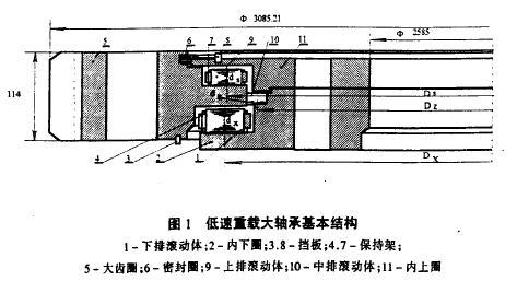
Big bearing structure of low speed and heavy loading diagram (see figure 1. Note: the bearing common in continuous caster ladle revolving platform), it has 3 three rows of cylindrical roller diameter, the upper and lower ring set of raceway, the outside part is the big gear ring. Large bearing work, up and down two rows by the cage is in horizontal rolling body mainly bear axial load and tilting moment, vertically out of rolling body mainly bear radial load (load about 300 t), and regulated low speed (usually 1 r/min), rotary discontinuity.
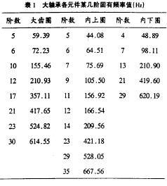
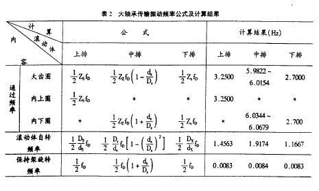
On microcomputer using ALGOR FEAS software, each element of large bearing natural frequency for theoretical calculation of income a few order natural frequency value shown in table 1, the after the validation of the theoretical calculation results. Application of kinematics principle of large bearing vibration frequency transmission formula is deduced and the calculation results are shown in table 2. Through calculation results see big bearing its transmission of low speed and heavy loading vibration frequency and inherent frequency of every element were generally low rolling bearing, analyzes the test signal, the fault signal is easy to be manufactured as low frequency interference signal to eliminate false negatives, miscalculation, so it is necessary to carry out the test signal demodulation. (mem)
2 the Hilbert Transform (Hilbert Transform) principle and the realization of the signal envelope
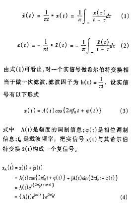
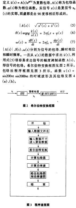
With the development of the digital system, there are many ways which can realize envelope technology, one of the Hilbert transform is realized software from the envelope of a typical algorithm. Hilbert transform is - the corresponding mapping relationship of the same domain. A continuous signal x (t) of the Hilbert transform for x (t), the positive and negative transformation is defined as:
3 envelope analysis of vibration signal
Vibration method at present is relatively mature in the equipment failure, the method of monitoring of rolling bearing fault also has a lot of successful examples. This article take big bearing fault vibration signal analysis of the acceleration peak and RMS values as parameters, and carries on the FFT analysis. The time domain signal and power spectrum diagram as shown in figure 5 (a), (b). After the envelope of the signal processing of spectrum analysis as shown in figure 5 (c), can be seen from the figure 5 (a) time domain signals characterized by impact, and amplitude modulation, shows great bearing some components produce spalling failure; The figure 5 (b) the frequency of the power spectrum graph and table 1 big bearing corresponding natural frequency of each element from the inherent frequency of quantity and energy spectrum diagram, the frequency of the largest share in the big gear ring and the inside circle of natural frequency and energy spectra of large frequency close to conclude that the big gear ring and the inside circle of spalling failure; See figure 5 (c) found that only 4 hz frequency components is outstanding, and the frequency components corresponding energy is larger. Table 2 illustrates the line of large bearing roller on the big gear ring and the inside circle through frequency of 3.25 Hz, and the measured frequency and the frequency is close to, this suggests that the large gear ring and inner ring raceway surface produced a fault, rolling body caused by fault surface impact generated by low frequency envelope method "demodulation". The conclusion is confirmed after the big bearing overhaul.
4 envelope analysis of acoustic emission signals
4.1 acoustic emission test system
Acoustic Emission (& Emission, AE) is the material load and internal force under the action of outside, in the form of elastic wave phenomenon of strain energy release. Acoustic emission can provide material microscopic deformation and cracking and crack occurrence and development of dynamic information. The emergence of the acoustic emission to meet two conditions: one is the material should be subjected to external load; The second is uneven or defective material internal structure. When the crack formation and the expansion of the material to produce sudden type acoustic emission signal. Often as a result of acoustic emission activity in material damage occurs before, so according to the characteristics of acoustic emission and the emission intensity, not only can be speculated that acoustic emission source of current status, and to study the history of its formation, and forecast the development trend, and thus for the state monitoring and fault diagnosis.

At present a lot of field application of acoustic emission, but put it for such a big bearing fault monitoring, it seems, are still rare. Based on the acoustic emission technology development status and the site operation state, large bearing through the selection of reasonable parameters, constitute a large bearing acoustic emission test system. The system is composed of four independent signals channel, the structure diagram of each channel is shown in figure 6.
Selected frequency acoustic emission sensor for the resonant sensor is 150 hz, because of its output signals are usually a few microvolts to several millivolt, so the following amplifier always gain must reach 50-100 db. This system implemented by preamplifier and main amplifier, preamplifier (40 db) for a fixed gain low noise amplifier with high input impedance, the main amplifier for the linear amplifier, the gain 0-60 db, it can be set by programming, adjust the interval is 5 db. The main amplifier with an adjustable threshold level knob, full scale is 5 V, every rotation increased or decreased by 0.5 V, according to the actual situation of the scene setting threshold (namely equipment normal operation, no ringing the location of the output), namely the signal to noise suppression, and make sure the useful signal. Using passband range 100 KHZ to 200 KHZ band pass filter, stop-band attenuation octave is greater than 20 db, so outside the pass band frequency components as to eliminate noise interference. As much as possible in order to reduce the sensor output signal attenuation and interference, the distance of the sensor and preamplifier choose 1.5 m.
4.2 acoustic emission signal analysis
Four way by the main amplifier output signal each road has three forms; The acoustic emission, envelope detection signal and original signal pulse signal. Select envelope signal mainly consider the following factors: first, the acoustic emission signal and original signal envelope of than belong to the low frequency signal, its post processing and A/D conversion is much easier than original acoustic emission signal processing, to facilitate the monitoring and diagnosis; Second, envelope of acoustic emission signal can be used as energy analysis, this paper take E =
To calculate the acoustic emission signal energy and the energy per unit time; Third, considering the large bearing due to the characteristics of low speed and heavy loading, acoustic emission signals are likely to be low speed, low failure frequency modulation, so do with the envelope signal spectrum analysis is more advantageous to the large bearing fault signal analysis.
The acoustic emission signal envelope power harmonic diagram as shown in figure 7. See from the spectrum diagram, (1) the measured frequency in every element of large bearing natural frequency can be found in the table with the corresponding components, every element was big bearing rolling surface produced a fault, but from all the components of the corresponding frequency components of energy and turned on, the number of natural frequency on the big gear ring and the inside circle of fault serious some; (2) the measured frequency of 7.32 Hz doubts about computing in front of the roller on the big gear ring and the inside circle through the double frequency, shows that large gear ring and inner ring rolling surface produced a fault, rolling body and fault surface touch grinding repetition frequency is shown; (3) by a principle of acoustic emission the acoustic emission signals of crack, flake and wear fault sensitive, thus determine bearing components produced a flake or wear out failure. The above analysis result was confirmed after overhaul at the scene.
5 conclusion
(1) based on the large bearing dynamic characteristics of low speed and heavy loading, the fault signal characteristic, the vibration signals and acoustic emission signal from software and hardware implementation envelope respectively, and the envelope signal spectrum analysis and diagnosis of the region and the type of bearing fault, with the scene after the overhaul for the bearing of the actual fault compared to prove in this paper, diagnosis result is correct.
(2) the acoustic emission method first applied in monitoring and fault diagnosis system of large bearing, in this paper, the resonant sensor, gain amplification, envelope detection and microcomputer testing system is feasible. Signal processing used in the envelope spectrum analysis can obviously reflect the type and the location of a large bearing fault. This in the later big bearing was observed after the overhaul is confirmed in practice.
(3) in this paper, the compilation of the Hilbert transform envelope analysis procedures, can be used as the future of this kind of bearing fault diagnosis.
References (abbreviated)


Scanning
 Blog
Blog